- GD&T
GENERAL DIMENSIONING- International Paper Size Standards
- Technical Drawing Styles
- ISO And ANSI Projections
- ANSI Technical Drawing Views
- Technical Drawing Dimesioning Types
- ANSI and ISO Geometric Tolerancing Symbols
- Geometric Tolerancing Reading
- Taylor Principle Rule#1
- Form Tolerances
- Profile Tolerances
- Orientation Tolerances
- Location Tolerances
- Runout Tolerances
- TOLERANCES
ANSI AND ISO- Tolerancing and Engineering Standards
- Hole and Shaft Basis Limits And Fits
- ISO International System For Limits And Fits
- International Tolerance Grade (IT)
- Fundamental Deviations For Hole and Shaft Basis
- ISO Tolerance Band IT01-IT16
- Calculation Of International Tolerance
- Calculation of Upper and Lower Deviation For Shaft
- Calculation of Upper and Lower Deviation For Holes
- ISO Shaft Tolerances (3mm-400mm)
- ISO Shaft Tolerances (400mm-3150mm)
- ISO Hole Tolerances (3mm-400mm)
- ISO Hole Tolerances (400mm-3150mm)
- ANSI Standard Limits and Fits
- METAL CUTTING TECHNOLOGIES
- Terms and Definitions of the Cutting Tools
- Cutting Tool Materials
- Selection of Carbide to machine the work-part
- Identification System For Indexable Inserts
- Work-Part Materials
- Machinability and the specific cutting force
- Machinability of the Certain Material Evaluations
- Cutting Forces and Chip Formations
Geometric Dimensioning And Tolerancing Reading
Geometric Dimensioning And Tolerancing reading is very important to understand detailed drawings. It helps to read drawings for engineers, designers, manufacturers etc. what surface has to be machined carefully. Geometric tolerancing reading helps to understand to specify and control the form, location and orientation of the features of components and manufactured parts. Geometric Dimensioning and Tolerancing is an efficient method for describing the tolerancing mandated by the designer of the part. The Datum axis or Datum planes are to be used for locating other features. With GD&T all inspection will result in the same result. It will help to understand if the dimension is within or out of tolerance. Geometric Dimensioning and Tolerancing forces the designers to totally consider functions, manufacturing processes, and inspection methods. These explanations would be good answers to why GD&T should be used. Chosen geometric tolerance and modifier/modifiers will be shown in Tolerance Feature Indication/Feature Control Frame. Tolerance control frame is a rectangular symbol which contain indications that define the geometrical tolerance for features. Geometric Tolerance defines the form and the size of a tolerance zone. Tolerance zone may be one of the followings; the area within circle, the space between two coaxial cylinders, the area between two parallel lines, the space within a cylinder, the space between two parallel surfaces or two parallel planes the space within a geometrically a square or rectangular prism or a solid with six faces, the area between two concentric circles,
Tolerance Feature Indication/Feature Control Frame Symbol.
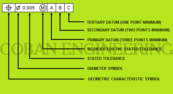
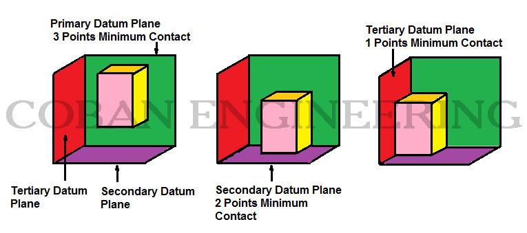
Primary Datum, Secondary Datum, and Tertiary Datum Planes: Datums must be perpendicular to each other.
Primary Datum Plane: The primary datum is selected to provide functional relationships, standardizations and repeatability between surfaces. A standardization of size is desired in the manufacturing of a part. Consideration of how parts are orientated to each other is very important. The chosen primary datum must insure precise measurements.
Secondary Datum Plane: Secondary datums are produced perpendicular to the primary datum so measurements can be referenced from them.
Tertiary Datum Plane: Tertiary datum is always perpendicular to both the primary and secondary datums ensuring a fixed position from three related parts.
Understanding of Geometric Tolerancing Modifiers
The Modifiers (MMC,LMC,RFS) are used to clarify implied tolerances. There are three directly implied modifiers to the tolerance value.
These are;
1-) Regardless of Feature Size (RFS)
2-) Maximum Material Condition (MMC)
3-) Least Material Condition (LMC)
The symbols for them can be found in the previous chart.
Regardless of Feature Size (RFS): RFS is the default modifier. so if there is no modifier symbol shown in feature control frame,
it means RFS is the default modifier. RFS is used when the size feature does not affect the specified tolerance.
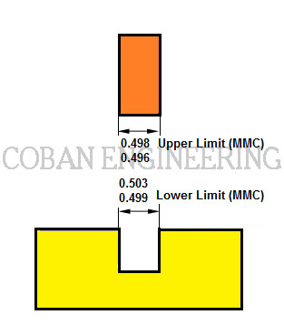
Maximum Material Condition (MMC): MMC can be used to constrain the tolerance on given dimension/dimensions.
MMC can be defined as the condition of a part feature where the maximum amount of material is required.
MMC is also used to maintain clearance and fit between shafts and holes.
With MMC, The given tolerance will be applied as
Maximum shaft diameter and Minimum hole diameter.
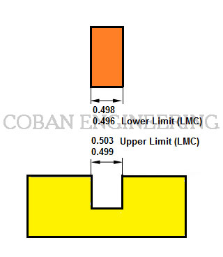
Least Material Condition (LMC): LMC condition where a size feature contains the least/minimum amount of material within the stated limits of size.
LMC can be defined as the condition of a part feature where the least/minimum amount of material is required.
With LMC, The given tolerance will be applied as Least/Minimum shaft diameter and Maximum hole diameter.


Copyright ©2010-2023 Coban Engineering.All Rights Reserved.