- GD&T
GENERAL DIMENSIONING- International Paper Size Standards
- Technical Drawing Styles
- ISO And ANSI Projections
- ANSI Technical Drawing Views
- Technical Drawing Dimesioning Types
- ANSI and ISO Geometric Tolerancing Symbols
- Geometric Tolerancing Reading
- Taylor Principle Rule#1
- Form Tolerances
- Profile Tolerances
- Orientation Tolerances
- Location Tolerances
- Runout Tolerances
- TOLERANCES
ANSI AND ISO- Tolerancing and Engineering Standards
- Hole and Shaft Basis Limits And Fits
- ISO International System For Limits And Fits
- International Tolerance Grade (IT)
- Fundamental Deviations For Hole and Shaft Basis
- ISO Tolerance Band IT01-IT16
- Calculation Of International Tolerance
- Calculation of Upper and Lower Deviation For Shaft
- Calculation of Upper and Lower Deviation For Holes
- ISO Shaft Tolerances (3mm-400mm)
- ISO Shaft Tolerances (400mm-3150mm)
- ISO Hole Tolerances (3mm-400mm)
- ISO Hole Tolerances (400mm-3150mm)
- ANSI Standard Limits and Fits
- METAL CUTTING TECHNOLOGIES
- Terms and Definitions of the Cutting Tools
- Cutting Tool Materials
- Selection of Carbide to machine the work-part
- Identification System For Indexable Inserts
- Work-Part Materials
- Machinability and the specific cutting force
- Machinability of the Certain Material Evaluations
- Cutting Forces and Chip Formations
Cylindricity:
Cylindricity is a condition of a manufacturing part surface of revolution in where all points of the circular surface are equi-distant from actual axis. Cylindricity tolerance is applies where cylindrical part features must have good circularity, straightness and taper. Thus Cylindricity tolerance applies both longitudinal and circular element of the surface. Cylindricity tolerance is applied to an individual surface, cylidricity tolerance does not need to be related to a datum. Cylindricity tolerance controls the entire surface of a cylinder.
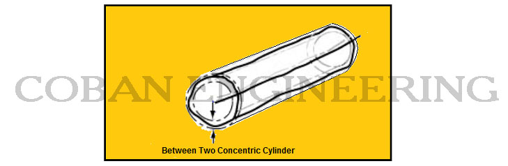
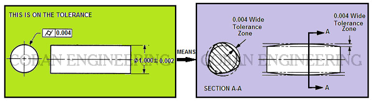
In the Cylidricity tolerance zone, the cylindrical surface must lie between two concentric/coaxial cylinders,the based on given cylindricity tolerance zone is 0.004 as shown in the example above. The surface must lie within given tolerance limits.
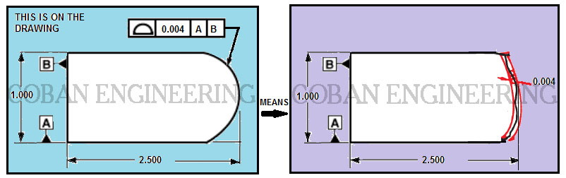
PROFILE TOLERANCES
Profile tolerances can be state by two tolerance zone. These are Line Profile and Surface Profile. Profile Tolerance can be defined a profile of a line or profile of surface generated by off setting each point on the nominal surface in a direction normal to the nominal surface at that point. A Profile is the outline of an object in a given plane. Profile tolerance also defines a uniform boundary around a surface within where the elements of the surface must lie. Profile is a three-dimensional tolerance that applies in all directions regardless of the drawing view where the tolerance is specified. Profile tolerances can be applied either unilateral or bilateral. Profile tolerances can control the location, orientation, size and form of a feature. The profile elements are curved lines, straight lines, and areas. The actual profile of the surface can be defined by basic radii dimensions, coordinate dimensions, angular dimensions. MMC and LMC are not used in the feature control frame with the profile symbol.
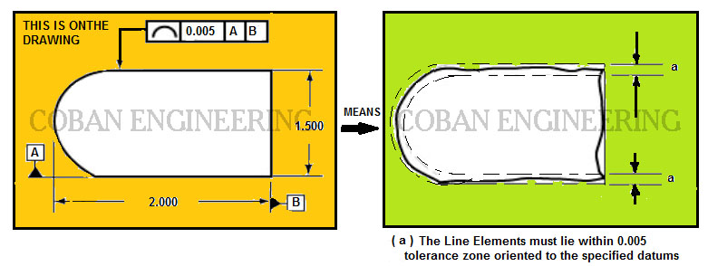
Line Profile:
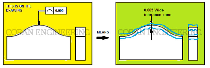
Profile line tolerance is two-dimensional tolerance that limits the amount of error for line elements relative to their true profile. Profile tolerance zone is two uniform lines applied at any cross-section of the surface. it used in situations where parts or objects have changing cross sections throughout the length (Ex. aircraft wing. Datums are normally used, but are not required (in cases when the only requirement is the profile shape taken at various cross section); if datum references are specified, the line elements are oriented relative to the datums specified; if no datum references are specified. The line elements are being controlled for form only assumed to be equal bilateral unless otherwise specified. The major focus point is that profile of a line establishes a two-dimensional tolerance zone that controls individual line elements of a feature or surface.
Second Example
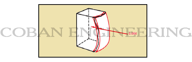
Surface Profile:
Profile of a surface is a three-dimensional tolerance. Surface profile tolerance limits the amount of error a surface can have relative to its true profile. Common applications for profile of a surface include controlling the size, location, orientation and/or form (or any combination of the aforementioned) of a planar, curved, or irregular surfaces, like polygons, cylinders, surfaces of revolution, or cones, and coplanar surfaces. Datums are normally used, but are not required, if datums are not referenced, the tolerance only limits the form of the profile; if three datums are referenced, the tolerance limits the form, location, and orientation. Tolerance zone is bilateral unless otherwise specified. it can be specified between two points or all-around using the same method for profile of a line between two points. Profile callout (feature control frame) is applied to a true profile on the drawing. The true profile is related to the datums reference with basic dimensions. Surface profile all around used for surfaces that have a constant, uniform cross-section shown on drawing by using the ‘ALL AROUND’ symbol on the leader connecting the feature control frame to the profile. Result is a tolerance zone consisting of two parallel boundaries equal in width to the tolerance. The tolerance zone should be perpendicular to a datum plane.


Copyright ©2010-2023 Coban Engineering.All Rights Reserved.