- GD&T
GENERAL DIMENSIONING- International Paper Size Standards
- Technical Drawing Styles
- ISO And ANSI Projections
- ANSI Technical Drawing Views
- Technical Drawing Dimesioning Types
- ANSI and ISO Geometric Tolerancing Symbols
- Geometric Tolerancing Reading
- Taylor Principle Rule#1
- Form Tolerances
- Profile Tolerances
- Orientation Tolerances
- Location Tolerances
- Runout Tolerances
- TOLERANCES
ANSI AND ISO- Tolerancing and Engineering Standards
- Hole and Shaft Basis Limits And Fits
- ISO International System For Limits And Fits
- International Tolerance Grade (IT)
- Fundamental Deviations For Hole and Shaft Basis
- ISO Tolerance Band IT01-IT16
- Calculation Of International Tolerance
- Calculation of Upper and Lower Deviation For Shaft
- Calculation of Upper and Lower Deviation For Holes
- ISO Shaft Tolerances (3mm-400mm)
- ISO Shaft Tolerances (400mm-3150mm)
- ISO Hole Tolerances (3mm-400mm)
- ISO Hole Tolerances (400mm-3150mm)
- ANSI Standard Limits and Fits
- METAL CUTTING TECHNOLOGIES
- Terms and Definitions of the Cutting Tools
- Cutting Tool Materials
- Selection of Carbide to machine the work-part
- Identification System For Indexable Inserts
- Work-Part Materials
- Machinability and the specific cutting force
- Machinability of the Certain Material Evaluations
- Cutting Forces and Chip Formations
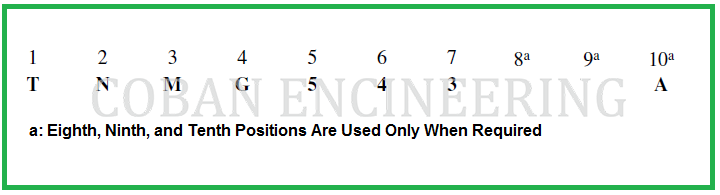
IDENTIFICATION SYSTEM FOR INDEXABLE INSERTS:
The size of indexable inserts is determined by the diameter of an I.C. (inscribed circle), except for rectangular and parallelogram inserts where the length and width dimensions are used. To describe an insert in its entirety, a standard ANSI B212.4-1986 identification system is used where each position number designates a feature of the insert. The ANSI Standard includes items now commonly used and facilitates identification of items not in common use. Identification consists of up to ten positions; each position defines a characteristic of the insert as shown below:
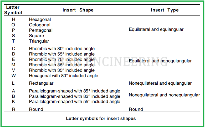
1) Insert Shape: The shape of an insert is designated by a letter: R for round; S, square; T, triangle; A, 85° parallelogram; B, 82° parallelogram; C, 80° diamond; D, 55° diamond; E, 75° diamond; H, hexagon; K, 55° parallelogram; L, rectangle; M, 86° diamond; O, octagon; P, pentagon; V, 35° diamond; and W, 80° trigon. ANSI B212.5-2002
2) Insert Relief Angle (Clearances): The second position is a letter denoting the relief angles; N for 0°; A, 3°; B, 5°; C, 7°; P, 11°; D, 15°; E, 20°; F, 25°; G, 30°; H, 0° & 11°*; J, 0° & 14°*; K, 0° & 17°*; L, 0° & 20°*; M, 11° & 14°*; R, 11° & 17°*; S, 11° & 20°*. When mounted on a holder, the actual relief angle may be different from that on the insert. ( * ) Second angle is secondary facet angle, which may vary by -/+ 1°.
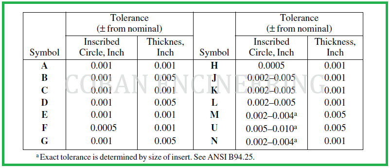
3) Insert Tolerances: The third position is a letter and indicates the tolerances which control the indexability of the insert. Tolerances specified do not imply the method of manufacture.
4) Insert Type: The type of insert is designated by a letter. A, with hole; B, with hole and countersink; C, with hole and two countersinks; F, chip grooves both surfaces, no hole; G, same as F but with hole; H, with hole, one countersink, and chip groove on one rake surface; J, with hole, two countersinks and chip grooves on two rake surfaces; M, with hole and chip groove on one rake surface; N, without hole; Q, with hole and two countersinks; R, without hole but with chip groove on one rake surface; T, with hole, one countersink, and chip groove on one rake face; U, with hole, two countersinks, and chip grooves on two rake faces; and W, with hole and one countersink. Note: a dash may be used after position 4 to separate the shape-describing portion from the following dimensional description of the insert and is not to be considered a position in the standard description
5) Insert Size: The size of the insert is designated by a one- or a two-digit number. For regular polygons and diamonds, it is the number of eighths of an inch in the nominal size of the inscribed circle, and will be a one- or two-digit number when the number of eighths is a whole number. It will be a two-digit number, including one decimal place, when it is not a whole number. Rectangular and parallelogram inserts require two digits: the first digit indicates the number of eighths of an inch width and the second digit, the number of quarters of an inch length.


Copyright ©2010-2023 Coban Engineering.All Rights Reserved.