- GD&T
GENERAL DIMENSIONING- International Paper Size Standards
- Technical Drawing Styles
- ISO And ANSI Projections
- ANSI Technical Drawing Views
- Technical Drawing Dimesioning Types
- ANSI and ISO Geometric Tolerancing Symbols
- Geometric Tolerancing Reading
- Taylor Principle Rule#1
- Form Tolerances
- Profile Tolerances
- Orientation Tolerances
- Location Tolerances
- Runout Tolerances
- TOLERANCES
ANSI AND ISO- Tolerancing and Engineering Standards
- Hole and Shaft Basis Limits And Fits
- ISO International System For Limits And Fits
- International Tolerance Grade (IT)
- Fundamental Deviations For Hole and Shaft Basis
- ISO Tolerance Band IT01-IT16
- Calculation Of International Tolerance
- Calculation of Upper and Lower Deviation For Shaft
- Calculation of Upper and Lower Deviation For Holes
- ISO Shaft Tolerances (3mm-400mm)
- ISO Shaft Tolerances (400mm-3150mm)
- ISO Hole Tolerances (3mm-400mm)
- ISO Hole Tolerances (400mm-3150mm)
- ANSI Standard Limits and Fits
- METAL CUTTING TECHNOLOGIES
- Terms and Definitions of the Cutting Tools
- Cutting Tool Materials
- Selection of Carbide to machine the work-part
- Identification System For Indexable Inserts
- Work-Part Materials
- Machinability and the specific cutting force
- Machinability of the Certain Material Evaluations
- Cutting Forces and Chip Formations
METAL CUTTING TECHNOLOGY
Material Cutting Technology is a manufacturing process in which a cutting tool is used to remove material from a work-part. So that the remaining material becomes a desired final shape and size by a controlled material-removal processes. The machining process is controlled by detail drawing. Machining is a family of processes. Machining common features are the use of cutting tools to form chips that are removed from the work-part. In manufacturing, metal parts frequently require machining. The cutting action itself is a shear deformation on the work-part. Machining can be applied to a wide variety of work materials all solid metals, plastics and plastic composites, woods and even most ceramics in spite of their high hardness and brittleness etc.
To remove material of the work-part (to perform cutting operations) and relative motions are required between the cutting tools and work-part. The relative motion is a combination of a primary motion called the Cutting Speed (v) and a secondary motion called the Feed (f). In addition, the penetration of the cutting tools below the original work surface is called the DOC (Depth of Cut (d) ) The cutting conditions can be defined as combination of the Speed, Feed, and DOC.
Machining can be performed by cutting tools. A machining process start with holding cutting tools on proper holder, position the cutting tools relative to the work, and provide power for the machining process at the proper speed, feed, and depth of cut. Machine Tools (Mill,Lathe, etc.) cause the motion of the work-part and the cutting tool that leads to the cutting of the work- part. Generally, each cutting tool makes a certain shape, such as flat plane, holes, cylinders etc. By controlling the cutting tools, work-part, and cutting conditions, machine tools permit parts to be made with great accuracy and repeatability to specified tolerances on the detail drawing.
Material removing operations usually divided into two categories: distinguished by purpose and cutting conditions: Roughing and Finishing cuts. In production machining jobs, one or more roughing cuts are usually performed on the work, followed by one or two finishing cuts. Roughing cuts are used to remove large amounts of material from the starting work-piece as rapidly as possible in order to produce a shape close to the desired form in specified tolerances, but leaving some material on the piece for a subsequent finishing operation. Roughing operations are performed at high feeds and slow feed. Cutting speeds are lower in roughing than in finishing. Finishing cuts are used to complete the part to achieve the final dimensions, tolerances, and surface finishes.
Theory behind of the material removing technology; plastically deform a metal material using a hard tool in order to obtain desired physical shape and properties. Physical phenomenon in metal machining are plastic flow, fracture, friction, heat, molecular diffusion, chatter, force relation between cutting tool and work-part, shear force of the tool etc. Material removing categories are machining; material removal by a sharp cutting tool, e.g., turning, milling, drilling etc. Abrasive processes; material removal by hard, abrasive particles, e.g., grinding. Non-traditional processes; various energy forms other than sharp cutting tool to remove material. Material removing categories would not be limited steps are given above. Material removing can be done by using laser, water jet cut, EDM, etc.
Cutting Tools Geometry, Basics and Definitions.
Implementing the results of any study on the tribology (the science and technology of friction, lubrication and wear; most often applied to the design of bearings ) the science and technology of friction, lubrication and wear; most often applied to the design of bearings of metal cutting in the right direction, Manufacturer should clearly understand the geometry of the cutting tool used. A proper understanding of cutting tool geometry enables one to determine the orientation of the cutting edge, rake and flank surfaces with respect to the cutting velocity, so that the actual rake, flank and inclination angles can be found for any given point of the cutting edges, despite the existence of national and ISO standards on tool geometry.
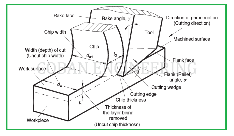
There are two basic types of metal cutting tools: single-point tools and multiple-cutting-edge tools. A single-point tool has one cutting edge. During machining, the point of the tool penetrates below the original work surface of the work-part. The point is usually rounded to a certain radius, called the nose radius. Multiple-cutting-edge tools have more than one cutting edge. Machinists use single-point cutting tools in operations like turning and multi-point tools in operations like sawing. A cutting tool has one or more sharp cutting edges. The cutting edge serves to separate a chip from the parent work material. Connected to the cutting edge are two surfaces of the tool: the rake face and the flank. The rake face, which directs the flow of the newly formed chip, is oriented a certain angle called the rake angle. The angle is measured relative to a plane perpendicular to the work surface. The rake angle can be negative or positive. The flank of the tool provides a clearance between the tool and the newly generated work surface, thus protecting the surface from abrasion, which would degrade the finish. This flank surface is oriented at an angle called the relief angle.
The following figure shows as an example for orthogonal cutting process.
Turning, boring, threading, shaping, and planning operations use single-point tools to remove metal. Turning operations rotate a cylindrical work-part and then move the cutting tool along the outside surface. Threading creates a spiral on the outside of a cylindrical piece. Boring operations insert a cutting tool into the end of a cylindrical work-part to make internal cuts. Shaping and planning operations create flat surfaces.
Milling, drilling, reaming, tapping, and broaching operations use multi-point cutting tools. Milling removes metal from a flat surface of a work-part. Drilling uses a long tool with cutting tips and twisted flutes to create holes. Reaming uses a drill-like tool to finish the surface of a hole that has already been drilled. Tapping uses a threaded tool to cut internal threads in a hole. Broaching uses a saw-like tool to cut and finish either an edge or a hole with one pass of the tool. In order to create a chip, cutting tools must be harder than the metal being cut. In order to achieve these properties, cutting tools are primarily made of tool either steels or carbides. These tools must also be strong and rigid enough to withstand the cutting forces
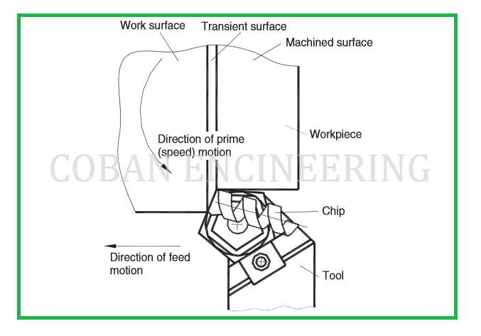
orthogonal cutting process or the two-dimensional is simplest cutting operation. It is one in which a straight-edged tool moves with a constant velocity in a direction perpendicular to the cutting edge of the tool. Turning operation is example for application a single-point cutting tool. The following figure shows as an example for single-point cutting process.


Copyright ©2010-2023 Coban Engineering.All Rights Reserved.