- GD&T
GENERAL DIMENSIONING- International Paper Size Standards
- Technical Drawing Styles
- ISO And ANSI Projections
- ANSI Technical Drawing Views
- Technical Drawing Dimesioning Types
- ANSI and ISO Geometric Tolerancing Symbols
- Geometric Tolerancing Reading
- Taylor Principle Rule#1
- Form Tolerances
- Profile Tolerances
- Orientation Tolerances
- Location Tolerances
- Runout Tolerances
- TOLERANCES
ANSI AND ISO- Tolerancing and Engineering Standards
- Hole and Shaft Basis Limits And Fits
- ISO International System For Limits And Fits
- International Tolerance Grade (IT)
- Fundamental Deviations For Hole and Shaft Basis
- ISO Tolerance Band IT01-IT16
- Calculation Of International Tolerance
- Calculation of Upper and Lower Deviation For Shaft
- Calculation of Upper and Lower Deviation For Holes
- ISO Shaft Tolerances (3mm-400mm)
- ISO Shaft Tolerances (400mm-3150mm)
- ISO Hole Tolerances (3mm-400mm)
- ISO Hole Tolerances (400mm-3150mm)
- ANSI Standard Limits and Fits
- METAL CUTTING TECHNOLOGIES
- Terms and Definitions of the Cutting Tools
- Cutting Tool Materials
- Selection of Carbide to machine the work-part
- Identification System For Indexable Inserts
- Work-Part Materials
- Machinability and the specific cutting force
- Machinability of the Certain Material Evaluations
- Cutting Forces and Chip Formations
RC7; Free Running Fits: This kind of fits are intended to use where accuracy is not essential. It is suitable for great temperature variations. This fits are suitable to use without any special requirements for precise guiding of shafts.
RC8 and RC9; Loose Running Fits: This kind of fits are intended for use where wide commercial tolerances may be required on the shaft. With this fits, The parts with great clearances with having great tolerances. Loose running fits exposed to effects of corrosion, contamination by dust and thermal or mechanical deformations.
Graphical Representation of ANSI B4.1-1967 Running and Sliding Fits Table
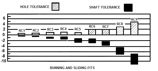
Running and Sliding Limits and Fits For Cylindrical Parts
[(ANSI B4.1-1967,R1987)]
All limits shown in chart below are in thousandths of an inches. Symbols H5,g5, etc. are Shaft and Hole designations used in American-British-Canadian System (ABC). Limits for Shaft and Hole are applied algebraically to the Nominal (basic) size to obtain the limits of the size for the parts. All data given in bold in the chart below are in accordance with ABC agreements. The values given under the "Clearance Limits Column" represent min and max amounts of clearance resulting from application of standard tolerance limits.
| VALUES SHOWN BELOW ARE IN THOUSANDTHS OF AN INCHES | |||||||||||||
| Nominal (Basic) Size Ranges (Inches) |
Class RC1 | Class RC2 | Class RC3 | Class RC4 | |||||||||
| Clearance Limits | Standard Tolerance Limits | Clearance Limits | Standard Tolerance Limits | Clearance Limits | Standard Tolerance Limits | Clearance Limits | Standard Tolerance Limits | ||||||
| Over | To | Hole H5 | Shaft g4 | Hole H6 | Shaft g5 |
Hole H7 | Shaft f6 | Hole H8 | Shaft f7 |
||||
| 0 | 0.12 | 0.1 0.45 | +0.2 0 | -0.1 -0.25 | 0.1 0.55 |
+0.25 0 | -0.1 -0.3 | 0.3 0.95 | +0.4 0 | -0.3 -0.55 | 0.3 1.3 |
+0.6 0 | -0.3 -0.7 |
| 0.12 | 0.40 | 0.15 0.5 | +0.2 0 | -0.15 -0.3 | 0.15 0.65 |
+0.3 0 | -0.15 -0.35 | 0.4 1.12 | +0.5 0 | -0.4 -0.7 | 0.4 1.6 |
+0.7 0 | -0.4 -0.9 |
| 0.24 | 0.40 | 0.2 0.6 | +0.25 0 | -0.2 -0.35 | 0.2 0.85 |
+0.4 0 | -0.2 -0.45 | 0.5 1.5 | +0.6 0 | -0.5 -0.9 | 0.5 2.0 |
+0.9 0 | -0.5 -1.1 |
| 0.40 | 0.71 | 0.25 0.75 | +0.3 0 | -0.25 -0.45 | 0.25 0.95 |
+0.4 0 | -0.25 -0.55 | 0.6 1.7 | +0.7 0 | -0.6 -1.0 | 0.6 2.3 |
+1.0 0 | -0.6 -1.3 |
| 0.71 | 1.19 | 0.3 0.95 | +0.4 0 | -0.3 -0.55 | 0.3 1.2 |
+0.5 0 | -0.3 -0.7 | 0.8 2.1 | +0.8 0 | -0.8 -1.3 | 0.8 2.8 |
+0.2 0 | -0.8 -1.6 |
| 1.19 | 1.97 | 0.4 1.1 | +0.4 0 | -0.4 -0.7 | 0.4 1.4 |
+0.6 0 | -0.4 -0.8 | 1.0 2.6 | +1.0 0 | -1.0 -1.6 | 1.0 3.6 |
+1.6 0 | -1.0 -2.0 |
| 1.97 | 3.15 | 0.4 0.2 | +0.5 0 | -0.4 -0.7 | 0.4 1.6 |
+0.7 0 | -0.4 -0.9 | 1.2 3.1 | +1.2 0 | -1.2 -1.9 | 1.2 4.2 |
+1.8 0 | -1.2 -2.4 |
| 3.15 | 4.73 | 0.5 1.5 | +0.6 0 | -0.5 -0.9 | 0.5 2.0 |
+0.9 0 | -0.5 -1.1 | 1.4 3.7 | +1.4 0 | -1.4 -2.3 | 1.4 5.0 |
+2.2 0 | -1.4 -2.8 |
| 4.73 | 7.09 | 0.6 1.8 | +0.7 0 | -0.6 -1.1 | 0.6 2.3 |
+1.0 0 | -0.6 -1.3 | 1.6 4.2 | +1.6 0 | -1.6 -2.6 | 1.6 5.7 |
+2.5 0 | -1.6 -3.2 |
| 7.09 | 9.85 | 0.6 2.0 | +0.8 0 | -0.6 -1.2 | 0.6 2.6 |
+1.2 0 | -0.6 -1.4 | 2.0 5.0 | +1.8 0 | -2.0 -3.2 | 2.0 6.6 |
+2.8 0 | -2.0 -3.8 |
| 9.85 | 12.41 | 0.8 2.3 | +0.9 0 | -0.8 -1.4 | 0.8 2.9 |
+1.2 0 | -0.8 -1.7 | 2.5 5.7 | +2.0 0 | -2.5 -3.7 | 2.5 7.5 |
+3.0 0 | -2.5 -4.5 |
| 12.41 | 15.75 | 1.0 2.7 | +1.0 0 | -1.0 -1.7 | 1.0 3.4 |
+1.4 0 | -1.0 -2.0 | 3.0 6.6 | +2.2 0 | -3.0 -4.4 | 3.0 8.7 |
+3.5 0 | -3.0 -5.2 |
| 15.75 | 19.69 | 1.2 3.0 | +1.0 0 | -1.2 -2.0 | 1.2 3.8 |
+1.6 0 | -1.2 -2.2 | 4.0 8.1 | +2.5 0 | -4.0 -5.6 | 4.0 10.5 |
+4.0 0 | -4.0 -6.5 |
| 19.69 | 30.09 | 1.6 3.7 | +1.2 0 | -1.6 -2.5 | 1.6 4.8 | +2.0 0 | -1.6 -2.8 |
5.0 10.0 | +3.0 0 | -5.0 -7.0 | 5.0 13.0 | +5.0 0 |
-5.0 -8.0 |
| 30.09 | 41.49 | 2.0 4.6 | +1.6 0 | -2.0 -3.0 | 2.0 6.1 | +2.5 0 | -2.0 -3.6 |
6.0 12.5 | +4.0 0 | -6.0 8.5 | 6.0 16.0 | +6.0 0 | -6.0 -10.0 |
| 41.49 | 56.19 | 2.5 5.7 | +2.0 0 | -2.5 -3.7 | 2.5 7.5 | +3.0 0 | -2.5 -4.5 |
8.0 16.0 | +5.0 0 | -8.0 -11.0 | 8.0 21.0 | +8.0 0 | -8.0 -13.0 |
| 56.19 | 76.39 | 3.0 7.1 | +2.5 0 | -3.0 -4.6 | 3.0 9.5 | +4.0 0 | -3.0 -5.5 |
10.0 20.0 | +6.0 0 | -10.0 -14.0 | 10.0 26.0 | +10.0 0 | -10.0 -16.0 |
| 76.39 | 100.9 | 4.0 9.0 | +3.0 0 | -4.0 -6.0 | 4.0 12.0 | +5.0 0 | -4.0 -7.0 |
12.0 25.0 | +8.0 0 | -121.0 -17.0 | 12.0 32.0 | +12.0 0 | -12.0 -20.0 |
| 100.9 | 131.9 | 5.0 11.5 | +4.0 0 | -5.0 -7.5 | 5.0 15.0 | +6.0 0 | -5.0 -9.0 | 16.0 32.0 |
+10.0 0 | -16.0 -22.0 | 16.0 42.0 | +16.0 0 | -16.0 -26.0 |
| 131.9 | 171.9 | 6.0 14.0 | +5.0 0 | -6.0 -9.0 | 6.0 19.0 | +8.0 0 | -6.0 -11.0 |
18.0 38.0 | +12.0 0 | -18.0 -26.0 | 18.0 50.0 | +20.0 0 | -18.0 -30.0 |
| 171.9 | 200 | 8.0 18.0 | +6.0 0 | -8.0 -12.0 | 8.0 22.0 | +10.0 0 |
-8.0 -12.0 | 22.0 48.0 | +16.0 0 | -22.0 -32.0 | 22.0 63.0 | +25.0 0 | -22.0 -38.0 |
All limits shown in chart below are in thousandths of an inches. Symbols H8,e7, etc. are Shaft and Hole designations used in American-British-Canadian System (ABC). Limits for Shaft and Hole are applied algebraically to the Nominal (basic) size to obtain the limits of the size for the parts. All data given in bold in the chart below are in accordance with ABC agreements. The values given under the "Clearance Limits Column" represent min and max amounts of clearance resulting from application of standard tolerance limits.
| VALUES SHOWN BELOW ARE IN THOUSANDTHS OF AN INCHES | ||||||||||||||||
| Nominal (Basic) Size Ranges (Inches) |
Class RC5 | Class RC6 | Class RC7 | Class RC8 | Class RC9 | |||||||||||
| Clearance Limits | Standard Tolerance Limits | Clearance Limits | Standard Tolerance Limits | Clearance Limits | Standard Tolerance Limits | Clearance Limits | Standard Tolerance Limits | Clearance Limits | Standard Tolerance Limits | |||||||
| Over | To | Hole H8 | Shaft e7 | Hole H9 | Shaft e8 |
Hole H9 | Shaft d8 | Hole H10 | Shaft c9 | Hole H11 | Shaft | |||||
| 0 | 0.12 | 0.6 1.6 | +0.6 0 | -0.6 -1.0 | 0.6 2.2 |
+1.0 0 | -0.6 -1.2 | 1.0 2.6 | -1.0 0 | -1.0 -1.6 | 2.5 5.1 |
+1.6 0 | -2.5 -3.5 | 4.0 8.1 | +2.5 0 | -4.0 -5.6 |
| 0.12 | 0.24 | 0.8 2.0 | +0.7 0 | -0.8 -1.3 | 0.8 2.7 |
+1.2 0 | -0.8 -1.5 | 1.2 3.1 | +1.2 0 | -1.2 -1.9 | 2.8 5.8 |
+1.8 0 | -2.8 -4.0 | 4.5 9.0 | +3.0 0 | -4.5 -6.0 |
| 0.24 | 0.40 | 1.0 2.5 | +0.9 0 | -1.0 -1.6 | 1.0 3.3 |
+1.4 0 | -1.0 -1.9 | 1.6 3.9 | +1.4 0 | -1.6 -2.5 | 3.0 6.6 |
+2.2 0 | -3.0 -4.4 | 5.0 10.7 | +3.5 0 | -5.5 -7.2 |
| 0.40 | 0.71 | 1.2 2.9 | +1.0 0 | -1.2 -1.9 | 1.2 3.8 |
+1.6 0 | -1.2 -2.2 | 2.0 4.6 | +1.6 0 | -2.0 -3.0 | 3.5 7.9 |
+2.8 0 | -3.5 -5.1 | 6.0 12.8 | +4.0 0 | -6.0 -8.8 |
| 0.71 | 1.19 | 1.6 3.6 | +1.2 0 | -1.6 -2.4 | 1.6 4.8 |
-2.0 0 | -1.6 -2.8 | 2.5 5.7 | +2.0 0 | -2.5 -3.7 | 4.5 10.0 |
+3.5 0 | -4.5 -6.5 | 7.0 15.5 | +5.0 0 | -7.0 -10.5 |
| 1.19 | 1.97 | 2.0 4.6 | +1.6 0 | -2.0 -3.0 | 2.0 6.1 |
+2.5 0 | -2.0 -3.6 | 3.0 7.1 | +2.5 0 | -3.0 -4.6 | 5.0 11.5 |
+4.0 0 | -5.0 -7.5 | 8.0 18.0 | +6.0 0 | -8.0 -12.0 |
| 1.97 | 3.15 | 2.5 3.5 | +1.8 0 | -2.5 -3.7 | 2.5 7.3 |
+3.0 0 | -2.5 -4.3 | 4.0 8.8 | +3.0 0 | -4.0 -5.8 | 6.0 13.5 |
+4.5 0 | -6.0 -9.0 | 9.0 20.5 | +7.0 0 | -9.0 -13.5 |
| 3.15 | 4.73 | 3.0 6.6 | +2.2 0 | -3.0 -4.4 | 3.0 8.7 |
+3.5 0 | -3.0 -5.2 | 5.0 10.7 | +3.5 0 | -5.0 -7.2 | 7.0 15.5 | -
-5.0 0 | -7.0 -10.5 | 10. 24.0 | -9.0 0 | -10.0 -15.0 |
| 4.73 | 7.09 | 3.5 7.6 | +2.5 0 | -3.5 -5.1 | 3.5 10.0 |
+4.0 0 | -3.5 -6.0 | 6.0 12.5 | +4.0 0 | -6.0 -8.5 | 8.0 18.0 |
+6.0 0 | -8.0 -12.0 | 12.0 28.0 | +10.0 0 | -12.0 -18.0 |
| 7.09 | 9.85 | 4.0 8.6 | +2.8 0 | -4.0 -5.8 | 4.0 11.3 |
+4.5 0 | -4.0 -6.8 | 7.0 14.3 | +4.5 0 | -7.0 -9.8 | 10. 21.5 |
+7.0 0 | -10.0 -14.5 | 15.0 34.0 | +12.0 0 | -15.0 -22.0 |
| 9.85 | 12.41 | 5.0 10.0 | +3.0 0 | -5.0 -7.0 | 5.0 13.0 |
+5.0 0 | -5.0 -8.0 | 8.0 16.0 | +5.0 0 | -8.0 -11.0 | 12.0 25.0 |
+8.0 0 | -12.0 -17.0 | 18.0 38.0 | +12.0 0 | -18.0 -26.0 |
| 12.41 | 15.75 | 6.0 11.7 | +3.5 0 | -6.0 -8.2 | 6.0 15.5 |
+6.0 0 | -6.0 -9.5 | 10.0 19.5 | +6.0 0 | -10.0 -13.5 | 14.0 29.0 |
+9.0 0 | -14.0 -20.0 | 22.0 45.0 | +14.0 0 | -22.0 -31.0 |
| 15.75 | 19.69 | 8.0 14.5 | +4.0 0 | -8.0 -10.5 | 8.0 18.0 |
+6.0 0 | -8.0 -12.0 | 12.0 22.0 | +6.0 0 | -12.0 -16.0 | 16.0 32.0 |
+10.0 0 | -16.0 -22.0 | 25.0 51.0 | +16.0 0 | -25.0 -35.0 |
| 19.69 | 30.09 | 10.0 18.0 | +5.0 0 | -10.0 -13.0 | 10.0 23.0 | +8.0 0 | -10.0 -15.0 |
16.0 29.0 | +8.0 0 | -16.0 -21.0 | 20.0 40.0 | +12.0 0 |
-20.0 -28.0 | 30.0 62.0 | +20.0 0 | -30.0 -40.0 |
| 30.09 | 41.49 | 12.0 22.0 | +6.0 0 | -12.0 -16.0 | 12.0 28.0 | +10.0 0 | -12.0 -18.0 |
20.0 36.0 | +10.0 0 | -20.0 -26.0 | 25.0 51.0 | +16.0 0 |
-25.0 -35.0 | 40.0 81.0 | +25.0 0 | -40.0 -56.0 |
| 41.49 | 56.19 | 16.0 29.0 | +8.0 0 | -16.0 -21.0 | 16.0 36.0 | +12.0 0 | -16.0 -24.0 |
25.0 45.0 | +12.0 0 | -25.0 -33.0 | 30.0 62.0 | +20.0 0 |
-30.0 -42.0 | 50.0 100.0 | +30.0 0 | -50. -70.0 |
| 56.19 | 76.39 | 20.0 36.0 | +10.0 0 | -20.0 -26.0 | 20.0 46.0 | +16.0 0 | -20.0 -30.0 |
30.0 56.0 | -16.0 0 | -30.0 -40.0 | 40.0 81.0 | +25.0 0 |
-40.0 -56.0 | 60.0 125.0 | +40.0 0 | -60.0 -85.0 |
| 76.39 | 100.9 | 25.0 45.0 | +12.0 0 | -25.0 -33.0 | 25.0 57.0 | +20.0 0 | -25.0 -37.0 |
40.0 72.0 | +20.0 0 | -40.0 -52.0 | 50.0 100.0 | +30.0 0 |
-50.0 -70.0 | 80.0 160.0 | +50.0 0 | -80.0 -110 |
| 100.9 | 131.9 | 30.0 56.0 | +16.0 0 | -30.0 -40.0 | 30.0 71.0 | +25.0 0 | -30.0 -46.0 |
50.0 91.0 | +25.0 0 | -50.0 -66.0 | 60.0 125.0 | +40.0 0 |
-60.0 -85.0 | 100 200 | +60.0 0 | -100 -140 |
| 131.9 | 171.9 | 35.0 67.0 | +20.0 0 | -35.0 -47.0 | 35.0 85.0 | +30.0 0 | -35.0 -55.0 |
60.0 110.0 | +30.0 0 | -60.0 -80.0 | 80.0 160 | +50.0 0 | -80.0 -110 |
130 260 | +80.0 0 | -130 -180 |
| 171.9 | 200 | 45.0 86.0 | +25.0 0 | -45.0 -61.0 | 45.0 110.0 | +40.0 0 |
-45.0 -75.0 | 80.0 145.0 | +40.0 0 | -80.0 -125 | 100 200 |
+60.0 0 | -100 -140 | 150 310 | +100 0 | -150 -210 |


Copyright ©2010-2023 Coban Engineering.All Rights Reserved.