- GD&T
GENERAL DIMENSIONING- International Paper Size Standards
- Technical Drawing Styles
- ISO And ANSI Projections
- ANSI Technical Drawing Views
- Technical Drawing Dimesioning Types
- ANSI and ISO Geometric Tolerancing Symbols
- Geometric Tolerancing Reading
- Taylor Principle Rule#1
- Form Tolerances
- Profile Tolerances
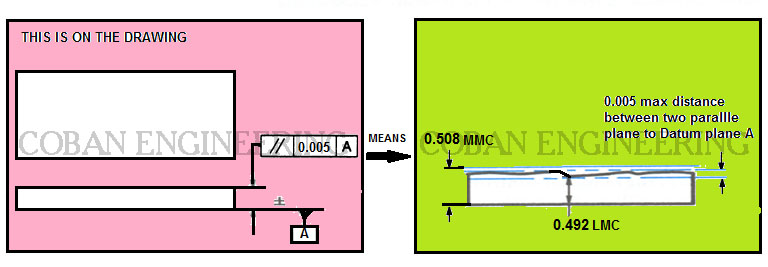
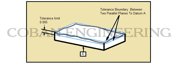
- Orientation Tolerances
- Location Tolerances
- Runout Tolerances
- TOLERANCES
ANSI AND ISO- Tolerancing and Engineering Standards
- Hole and Shaft Basis Limits And Fits
- ISO International System For Limits And Fits
- International Tolerance Grade (IT)
- Fundamental Deviations For Hole and Shaft Basis
- ISO Tolerance Band IT01-IT16
- Calculation Of International Tolerance
- Calculation of Upper and Lower Deviation For Shaft
- Calculation of Upper and Lower Deviation For Holes
- ISO Shaft Tolerances (3mm-400mm)
- ISO Shaft Tolerances (400mm-3150mm)
- ISO Hole Tolerances (3mm-400mm)
- ISO Hole Tolerances (400mm-3150mm)
- ANSI Standard Limits and Fits
- METAL CUTTING TECHNOLOGIES
- Terms and Definitions of the Cutting Tools
- Cutting Tool Materials
- Selection of Carbide to machine the work-part
- Identification System For Indexable Inserts
- Work-Part Materials
- Machinability and the specific cutting force
- Machinability of the Certain Material Evaluations
- Cutting Forces and Chip Formations
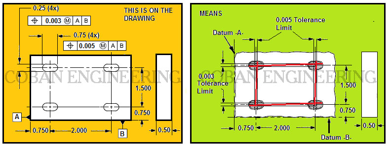
LOCATION TOLERANCES
Location Tolerances can be state by three tolerance zone. These are position, concentricity, and symmetry tolerances. Concentricity and symmetry are used to control the center distance of feature elements. Position is used to control coaxiality of features, the center distance between features, and the location of features as a group. position, concentricity, and symmetry tolerances are associated with datums. LMC or MMC can apply to feature of size
Symmetry:
Symmetry Tolerance controls the median points of a feature of size, symmetry tolerance is applied to non circular features. Symmetry Tolerance is a three-dimensional geometric tolerance that controls how much the median points between two features may deviate from a specified center plane or axis. This tolerance is similar to concentricity, and the verification of symmetry tolerance is likewise time-consuming and difficult. It is generally recommended that to use position, parallelism and straightness instead of it. Datum is used for this Tolerance. Symmetry is much like concentricity, except that it controls rectangular features and involves two imaginary flat planes, much like parallelism.
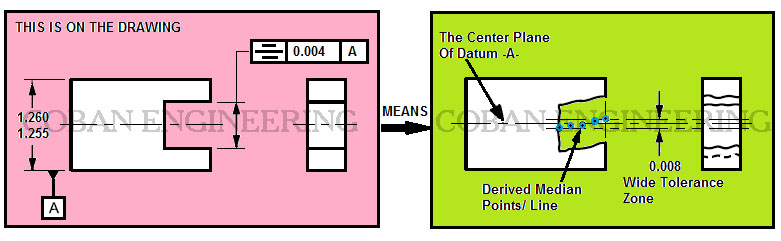
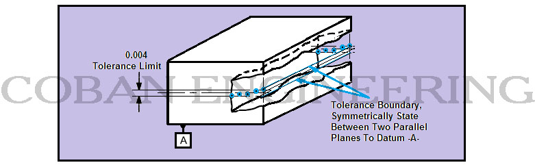
The median plane of the slot shall be contained between two parallel planes, which are 0.004 apart and symmetrically disposed about the median plane with respect to the datum feature A. The two plane are equally disposed about datum plane -A-. The symmetry of the part must be within specified tolerance limit. The tolerance zone is limited by two parallel planes a specified distance apart and disposed symmetrically to the median plane with respect to the datum axis or datum plane.
Positional:
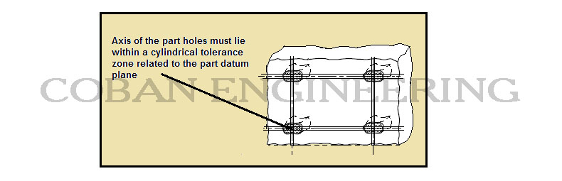
Positional tolerance is a three-dimensional geometric tolerance that controls how much the location of a feature can deviate from its true position. Positional tolerances are probably used more than any other geometric control. Positional tolerances is used to locate features of size from datum planes such as a hole or keyway and used to locate features coaxial to a datum axis. A position tolerance is the total permissible variation in the location of a feature about its exact true position. Positional tolerances for cylindrical features, the position tolerance zone is typically a cylinder within which the axis of the feature must lie. Positional tolerances for other features, the center plane of the feature must fit in the space between two parallel planes. The tolerance defines a zone that the axis or center plane of a feature of size may vary from. The concept is there is an exact or true position that the feature would be if it was made perfect however since nothing is made perfect a tolerance zone allows deviation from perfection. The exact position of the feature is located with basic dimensions. Datums are required. The true/exact location of a feature of size is defined by basic dimensions which is shown in a box and are established from datum planes or axes. When a material condition modifier is specified a boundary named virtual condition is established. It is located at the true position and it may not be violated by the surface or surfaces of the considered feature. Its size is determined by adding or subtracting depending on whether the feature is an external or an internal feature and whether the material condition specified. LMC or MMC can apply to feature of size apply to feature of size.


Copyright ©2010-2023 Coban Engineering.All Rights Reserved.