- GD&T
GENERAL DIMENSIONING- International Paper Size Standards
- Technical Drawing Styles
- ISO And ANSI Projections
- ANSI Technical Drawing Views
- Technical Drawing Dimesioning Types
- ANSI and ISO Geometric Tolerancing Symbols
- Geometric Tolerancing Reading
- Taylor Principle Rule#1
- Form Tolerances
- Profile Tolerances
- Orientation Tolerances
- Location Tolerances
- Runout Tolerances
- TOLERANCES
ANSI AND ISO- Tolerancing and Engineering Standards
- Hole and Shaft Basis Limits And Fits
- ISO International System For Limits And Fits
- International Tolerance Grade (IT)
- Fundamental Deviations For Hole and Shaft Basis
- ISO Tolerance Band IT01-IT16
- Calculation Of International Tolerance
- Calculation of Upper and Lower Deviation For Shaft
- Calculation of Upper and Lower Deviation For Holes
- ISO Shaft Tolerances (3mm-400mm)
- ISO Shaft Tolerances (400mm-3150mm)
- ISO Hole Tolerances (3mm-400mm)
- ISO Hole Tolerances (400mm-3150mm)
- ANSI Standard Limits and Fits
- METAL CUTTING TECHNOLOGIES
- Terms and Definitions of the Cutting Tools
- Cutting Tool Materials
- Selection of Carbide to machine the work-part
- Identification System For Indexable Inserts
- Work-Part Materials
- Machinability and the specific cutting force
- Machinability of the Certain Material Evaluations
- Cutting Forces and Chip Formations
Technical Drawing Line Types
Technical drawing Lines are used for different purposes to provide specific information for designers, manufacturers, etc. looking at the drawing. The person who will read drawings have to learn what they mean. Line types are also a language type to communicate between technical people.
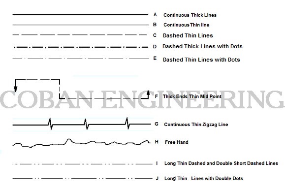
A; Continuous Thick Line: Surroundings and sides of the matters ( Outlines of the Edges), End of the Screws,
B; Continuous Thin line: Measure lines, Backside section lines, Implied axis lines, to state the code of the planes, at diagonal lines which are used to state plane surface, Intersection, Leader, Hatching.
C; Dashed Thin Lines: Invisible/Hidden Lines represents an invisible edges on the on an objects.
D; Dashed Thick Lines with Dots: To state the special places/surfaces which will processed additionally like to coat, to harden etc.
E; Dashed Thin Lines with Dots: Axis lines of symmetrical drawings, In front of section planes.
F; Chain Thin with Thick Ends: Cutting Plane, To draw the trace at section planes,
G; Continuous Thin Zigzag Line: It is used when free hand lines are drawn by tools
H; Free Hand Line: Limits of partial and interrupted views and sections
I; and J; Parts situated in front of the cutting planes, outlines of adjacent parts, Censorial Lines, to state center of gravity
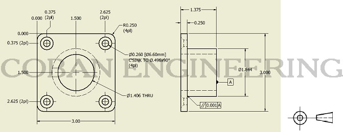
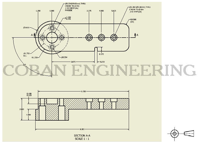
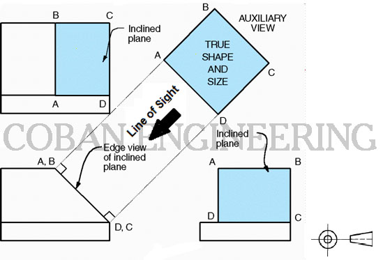
ANSI Technical Drawing Views
A: Projected Two View Drawing;
B: Section View; Section View allows Designer to show internal feature of the objects. Section View are highly useful in minimizing the number of projected views.
C: Auxiliary View; Auxiliary View are usually used to show inclined and oblique surface true size. inclined and oblique surface do not show true size in the standard views.


Copyright ©2010-2023 Coban Engineering.All Rights Reserved.