- GD&T
GENERAL DIMENSIONING- International Paper Size Standards
- Technical Drawing Styles
- ISO And ANSI Projections
- ANSI Technical Drawing Views
- Technical Drawing Dimesioning Types
- ANSI and ISO Geometric Tolerancing Symbols
- Geometric Tolerancing Reading
- Taylor Principle Rule#1
- Form Tolerances
- Profile Tolerances
- Orientation Tolerances
- Location Tolerances
- Runout Tolerances
- TOLERANCES
ANSI AND ISO- Tolerancing and Engineering Standards
- Hole and Shaft Basis Limits And Fits
- ISO International System For Limits And Fits
- International Tolerance Grade (IT)
- Fundamental Deviations For Hole and Shaft Basis
- ISO Tolerance Band IT01-IT16
- Calculation Of International Tolerance
- Calculation of Upper and Lower Deviation For Shaft
- Calculation of Upper and Lower Deviation For Holes
- ISO Shaft Tolerances (3mm-400mm)
- ISO Shaft Tolerances (400mm-3150mm)
- ISO Hole Tolerances (3mm-400mm)
- ISO Hole Tolerances (400mm-3150mm)
- ANSI Standard Limits and Fits
- METAL CUTTING TECHNOLOGIES
- Terms and Definitions of the Cutting Tools
- Cutting Tool Materials
- Selection of Carbide to machine the work-part
- Identification System For Indexable Inserts
- Work-Part Materials
- Machinability and the specific cutting force
- Machinability of the Certain Material Evaluations
- Cutting Forces and Chip Formations
GEOMETRIC DIMENSIONING AND TOLERANCING
Geometric dimensioning and tolerancing is a system to define geometric symbols to help Machine designer and Manufacturer to communicate each other over the detail drawings ( or MBD ( Model Based Definition). It is a system of symbols, rules and definitions used to define the geometry of mechanical parts. Geometric dimensioning and tolerancing provides a comprehensive system for symbolically defining the geometrical tolerance zone.
What is Technical Drawings?
Technical Drawing is a type of special universal graphic language used between Engineers (Mechanical, Electrical etc.), Architects, Drafters, Designers, CAD Operators. Technical Drawing is a universal language of engineering used in the design process for solving problems, quickly and accurately visualizing objects, and conducting analysis. Technical drawing is the formal and precise study of the procedures, tools, supplies, skills and techniques used to record and communicate the shape, size, features and precision of physical objects of a product. These experts are using views and numbers/dimensions that should be understood by anyone regardless of the language they speak. Technical drawing can be made by using CAD applications, Freehand or Mechanical methods. In order for drawing to be dimensioned and understood, we need follow standards that every company in the world must follow. These standards are ISO, ANSI, DIN, JIS,CEN (European Standards Organization), MIL, DOD(The United States military has two organizations that develop standards)etc.
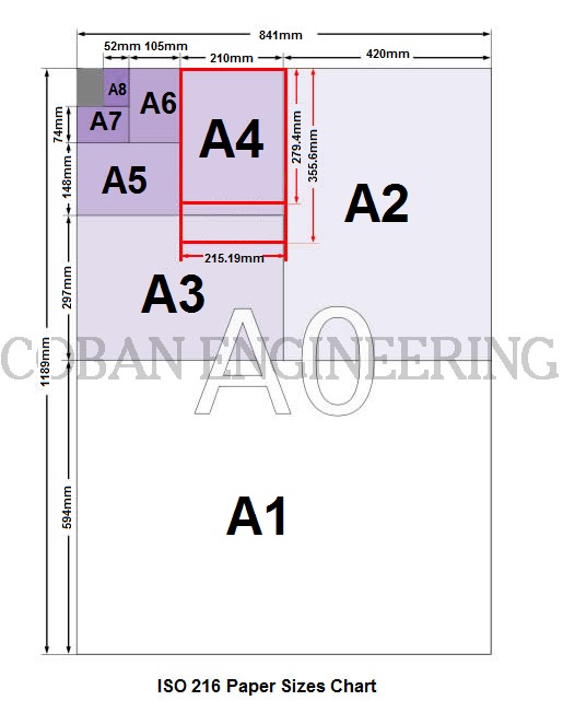
International Paper Size Standards
ISO 216 Paper Sizes: In the ISO Standard Paper Size System, the height-to-width ratio of all pages is the square root of two (√ 2 ). it is based on the German DIN 476 standard for paper sizes.ISO 216 standard paper sizes are based on the metric system.ISO 216 standard paper sizes shown in the following chart. ISO paper sizes can be defined with "A", "B" and "C" sizes. But we will give information about "A" series paper sizes.
| ISO Format | A series Paper Sizes | B series Paper Sizes | C series Paper Sizes | |||
| Size | Metric (mm) | Inch (in) | Metric (mm) | Inch (in) | Metric (mm) | Inch (in) |
| 4A0 | 1682 x 2378 | 66.22x93.62 | ||||
| 2A0 | 1189 x 1682 | 46.81x46.81 | ||||
| 0 | 841x1189 | 33.11x66.22 | 1000x1414 | 39.37x55.67 | 917x1297 | 36.10x51.06 |
| 1 | 594 x 841 | 23.39x33.11 | 707x1000 | 27.83x39.37 | 648x917 | 25.51x36.10 |
| 2 | 420x594 | 16.54x23.39 | 500x707 | 19.69x27.83 | 458x648 | 18.03x25.51 |
| 3 | 297x420 | 11.69x16.54 | 353x500 | 13.90x19.69 | 324x458 | 12.76x18.03 |
| 4 | 210x297 | 8.27x11.69 | 250x353 | 9.84x13.90 | 229x324 | 9.02x12.76 |
| 5 | 148x210 | 5.83x8.27 | 176x250 | 6.93x9.84 | 162x229 | 6.38x9.02 |
| 6 | 105x148 | 4.13x5.83 | 125x176 | 4.92x6.93 | 114x162 | 4.49x6.38 |
| 7 | 74x105 | 2.91x4.13 | 88x125 | 3.46x4.92 | 81x114 | 3.19x4.49 |
| 8 | 52x74 | 2.05x2.91 | 62x88 | 2.44x3.46 | 57x81 | 2.24x3.19 |
| 9 | 37x52 | 1.46x2.05 | 44x62 | 1.73x2.44 | 40x57 | 1.57x2.24 |
| 10 | 26x37 | 1.02x1.46 | 31x44 | 1.22x1.73 | 28x40 | 1.10x1.57 |
4A0 and 2A0 are the DIN 476 Oversize Formats. The paper sizes bigger than A0, 4A0 and 2A0, aren't formerly defined by ISO 216. But These are commonly used for oversized paper. The origin of these formats is in the German DIN 476 standard.ISO 216 was derived from DIN 476. There are some A series paper size tolerances used by ISO 216. These are ± 1.5 mm (0.06 in) for dimensions up to 150 mm (5.9 in, ± 2 mm (0.08 in) for lengths in the range 150 to 600 mm (5.9 to 23.6 in), and ± 3 mm (0.12 in) for any dimension above 600 mm (23.6 in).
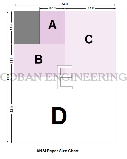
ANSI Standard Paper Sizes (ANSI/ASME Y14.1)
| ANSI | Size | Similar ISO A Sizes | |
| Metric (mm) | Inches | Metric (mm) | |
| ANSI A | 215.9 x 279.4 | 8.5 x 11 | A4 |
| ANSI B | 279.4 x 431.8 | 11 x 17 | A3 |
| ANSI C | 431.8 x 558.8 | 17 x 22 | A2 |
| ANSI D | 558.8 x 863.6 | 22 x 34 | A1 |
| ANSI E | 863.6 x 1117.6 | 34 x 44 | A0 |


Copyright ©2010-2023 Coban Engineering.All Rights Reserved.