- GD&T
GENERAL DIMENSIONING- International Paper Size Standards
- Technical Drawing Styles
- ISO And ANSI Projections
- ANSI Technical Drawing Views
- Technical Drawing Dimesioning Types
- ANSI and ISO Geometric Tolerancing Symbols
- Geometric Tolerancing Reading
- Taylor Principle Rule#1
- Form Tolerances
- Profile Tolerances
- Orientation Tolerances
- Location Tolerances
- Runout Tolerances
- TOLERANCES
ANSI AND ISO- Tolerancing and Engineering Standards
- Hole and Shaft Basis Limits And Fits
- ISO International System For Limits And Fits
- International Tolerance Grade (IT)
- Fundamental Deviations For Hole and Shaft Basis
- ISO Tolerance Band IT01-IT16
- Calculation Of International Tolerance
- Calculation of Upper and Lower Deviation For Shaft
- Calculation of Upper and Lower Deviation For Holes
- ISO Shaft Tolerances (3mm-400mm)
- ISO Shaft Tolerances (400mm-3150mm)
- ISO Hole Tolerances (3mm-400mm)
- ISO Hole Tolerances (400mm-3150mm)
- ANSI Standard Limits and Fits
- METAL CUTTING TECHNOLOGIES
- Terms and Definitions of the Cutting Tools
- Cutting Tool Materials
- Selection of Carbide to machine the work-part
- Identification System For Indexable Inserts
- Work-Part Materials
- Machinability and the specific cutting force
- Machinability of the Certain Material Evaluations
- Cutting Forces and Chip Formations
Terms and Definitions of the Cutting Tools
Cutting tool surfaces and elements are Shank, Flank Face, Rake face, Cutting edge, Cutting wedge, etc. Shank is the main body of the tool. If the tool is an inserted cutter type, the shank supports the cutter or bit. Cutting wedge is the tool body enclosed between the rake and the flank faces. Rake face is the surface over which the chip formed in the cutting process slides. Flank face is the surface(s) over which the surface produced on the work-part passes. These terms will be explained very deeply to have better understanding cutting tool surfaces and elements. The geometry of a cutting element is defined by certain basic tool angles and thus precise definitions of these angles are essential. A system of tool angles is shown in figure below and is known as the tool-in-hand system. Rake, wedge and flank angles are specified by γ, β and α, respectively, and these are identified by the subscript of the plane of intersection. The definitions of basic tool angles in the tool agles-in-hand system are as follows in figure:
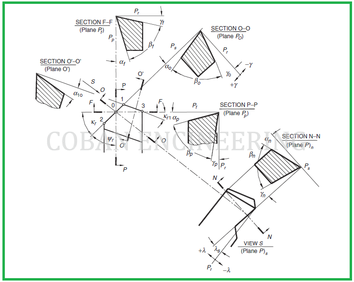
Tool approach angle: "ψ r" is the tool approach angle; it is an acute angle that "Ps" makes with "Pp" and is measured in the reference plane "Pr", as shown in the figure above
The rake angles: The rake angles are defined in the corresponding planes of measurement. The rake angle is the angle between the reference plane (the trace of which in the plane of measurement considered appears as the normal to the direction of primary motion) and the intersection line formed by the plane of measurement considered and the tool rake plane. The rake angle is defined as being acute and positive always when looking across the rake face from the selected point and along the line of intersection of the face and the plane of measurement. The line of intersection viewed lies on the opposite side of the tool reference plane from the direction of primary motion in the measurement plane for "γf", "γp" and "γo" or a major component of it appears in the normal plane for "γn" . The sign of the rake angles is well defined in the figure above.
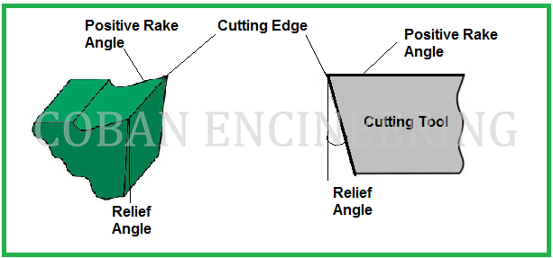
Positive Rake: If the inclination of the tool face is such as to make the cutting edge keener or more acute than when the rake angle is zero, the rake angle is defined as positive. See the figure below.
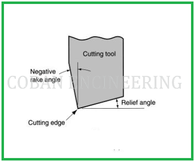
Negative Rake: If the inclination of the tool face makes the cutting edge less keen or more blunt than when the rake angle is zero, the rake is defined as negative. See the figure below.


Copyright ©2010-2023 Coban Engineering.All Rights Reserved.