- GD&T
GENERAL DIMENSIONING- International Paper Size Standards
- Technical Drawing Styles
- ISO And ANSI Projections
- ANSI Technical Drawing Views
- Technical Drawing Dimesioning Types
- ANSI and ISO Geometric Tolerancing Symbols
- Geometric Tolerancing Reading
- Taylor Principle Rule#1
- Form Tolerances
- Profile Tolerances
- Orientation Tolerances
- Location Tolerances
- Runout Tolerances
- TOLERANCES
ANSI AND ISO- Tolerancing and Engineering Standards
- Hole and Shaft Basis Limits And Fits
- ISO International System For Limits And Fits
- International Tolerance Grade (IT)
- Fundamental Deviations For Hole and Shaft Basis
- ISO Tolerance Band IT01-IT16
- Calculation Of International Tolerance
- Calculation of Upper and Lower Deviation For Shaft
- Calculation of Upper and Lower Deviation For Holes
- ISO Shaft Tolerances (3mm-400mm)
- ISO Shaft Tolerances (400mm-3150mm)
- ISO Hole Tolerances (3mm-400mm)
- ISO Hole Tolerances (400mm-3150mm)
- ANSI Standard Limits and Fits
- METAL CUTTING TECHNOLOGIES
- Terms and Definitions of the Cutting Tools
- Cutting Tool Materials
- Selection of Carbide to machine the work-part
- Identification System For Indexable Inserts
- Work-Part Materials
- Machinability and the specific cutting force
- Machinability of the Certain Material Evaluations
- Cutting Forces and Chip Formations
TOLERANCING AND ENGINEERING STANDARDS
Tolerancing is just like written languages. It has its own standards. There are to many standards like ANSI(Inch System), ISO (Metric System) etc. List of standards: ANSI B4.1, ANSI B4.2, ISO 286, ISO 1829, ISO 2768, EN 20286, JIS B 0401. In an assembly process the degree of "clearance" or "tightness" desired between mating parts is important. In a manufacture of a machine, quality is a primary consideration. Manufacturing precision taken into the product determines its quality, its cost and selling price. Parts of a machine are designed in order to make a function. The working parts have a definite relationship with each other: free rotation, free longitudinal movement, clamping action, and permanent fixed position. Precision is the degree of accuracy necessary to ensure the functioning of a part as intended. Tolerance is the allowable variation for any given size in order to achieve a proper function.
Tolerancing Definitions
NOMINAL SIZE : The size used for general description. Example; 7/8 inch Shaft, 25mm Shaft etc.
BASIC SIZE : The size used when the nominal size is converted to the decimal and from which deviation are made to produce limit dimension. Example: .8750inch shaft which is the basic size for a 7/8 inch nominal shaft.25mm nominal size which can be basic size of 24.950mm.
LIMIT DIMENSION : The Lower and Upper permitted sizes for a single feature dimension. 0.500-0.506 inch where 0.500 inch is the lower limit and 0.506 inch upper limit dimensions
TOLERANCE :Tolerance is the allowable variation for any given size in order to achieve a proper function. Tolerance equals the difference between lower and upper limit dimensions. Example; for 0.500-0.506 inch the tolerance would be 0.006 inch.
BILATERAL TOLERANCE : It is a way to express tolerance by using both minus and plus variations from a given size. Example; inch. The limit
dimensions are
1.120-1.130 inch. The tolerance is 0.010 inch.
UNILATERAL TOLERANCE : It is a way to express tolerance by
using only minus or plus variation from a given size. Example
 inch. As you can see the first case uses a minus variation.
or
 inch. The first case uses a minus and plus variation.
FIT : The general term of fit to describe the range of tightness designed into parts which assemble one into another. The fit can be explained under the three categories.
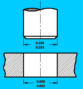
A-CLEARANCE FIT : A type of fit in which one part fits easily into another with a resulting clearance gap. See the below example,
A clearance fit. The shaft is always smaller than the hole
Tolerance on shaft : 0.002
Tolerance on hole : 0.002
minimum clearance : 0.600 - 0.595 = 0.005 inch
maximum clearance : 0.602 - 0.593= 0.009 inch
The 0.005 clearance in for the tightest possible fit.
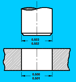
B-FORCE (INTERFERENCE) FIT : A type of fit in which one part must be forcibly fitted into another. See the below example
An Force (interference) fit. when the shaft is always larger in diameter than
the hole parts must be assembled by pressure or heat expansion.
Tolerance on shaft : 0.001
Tolerance on hole : 0.001
minimum clearance : 0.500 - 0.503= -0.003 in (the tightest fit 0.003 in interference)
maximum clearance : 0.501 - 0.502 = -0.001 in (the loosest fit 0.001 in interference)
Maximum clearance=Minimum interference
Minimum clearance=Maximum interference
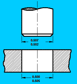
C-TRANSITION FIT : A type of fit in which loosest case provides a clearance fit and the tightest case gives an interference fit. See the example below,
A transition fit exist when the maximum clearance is positive and the minimum clearance is negative
Tolerance on shaft : 0.005
Tolerance on hole : 0.005
minimum clearance : 0.500 - 0.507 = -0.007 inch
The tightest fit is 0.007 in interference.
maximum clearance : 0.505 - 0.002 = 0.503 inch
The loosest fit is 0.003 in clearance
Transition fits are used only for locating a shaft relative to a hole,
where accuracy is important but either a clearance or interference is permitted.
ALLOWANCE : An alternative expression for tightest possible fit, which is minimum clearance or maximum interference

Maximum allowance is 0.003.
BASIC-SHAFT SYSTEM : This is a system in which the basic size is included as one of the limit dimensions of the shaft. But it is not for the hole. As an example: for a basis size of 1.000 inch. The limit dimensions on the shaft could be 1.000 and 1.005 inch. The related hole could be 1.011 and 1.018 inch.
BASIC-HOLE SYSTEM : This is a system in which the basic size appears as one of the limit dimensions of the hole. But it is not for the shaft. As an example for a basic size of 1.000 inch, the limit dimensions of the hole might be 1.000 and 1.007 inch. For the related shaft the limit dimensions could be 0.994 and 0.989 inch.
MINIMUM MATERIAL CONDITION : In this condition a hole is at its largest limit dimension. A shaft is at its smallest limit dimension. This condition exists at maximum clearance or minimum interference.
MAXIMUM MATERIAL CONDITION : In this condition a hole is at its smallest limit dimension. The shaft is at its largest limit dimension. This condition exists at minimum clearance or maximum interference. See example under the Force fit condition.
Copyright ©2010-2023 Coban Engineering.All Rights Reserved.


