- GD&T
GENERAL DIMENSIONING- International Paper Size Standards
- Technical Drawing Styles
- ISO And ANSI Projections
- ANSI Technical Drawing Views
- Technical Drawing Dimesioning Types
- ANSI and ISO Geometric Tolerancing Symbols
- Geometric Tolerancing Reading
- Taylor Principle Rule#1
- Form Tolerances
- Profile Tolerances
- Orientation Tolerances
- Location Tolerances
- Runout Tolerances
- TOLERANCES
ANSI AND ISO- Tolerancing and Engineering Standards
- Hole and Shaft Basis Limits And Fits
- ISO International System For Limits And Fits
- International Tolerance Grade (IT)
- Fundamental Deviations For Hole and Shaft Basis
- ISO Tolerance Band IT01-IT16
- Calculation Of International Tolerance
- Calculation of Upper and Lower Deviation For Shaft
- Calculation of Upper and Lower Deviation For Holes
- ISO Shaft Tolerances (3mm-400mm)
- ISO Shaft Tolerances (400mm-3150mm)
- ISO Hole Tolerances (3mm-400mm)
- ISO Hole Tolerances (400mm-3150mm)
- ANSI Standard Limits and Fits
- METAL CUTTING TECHNOLOGIES
- Terms and Definitions of the Cutting Tools
- Cutting Tool Materials
- Selection of Carbide to machine the work-part
- Identification System For Indexable Inserts
- Work-Part Materials
- Machinability and the specific cutting force
- Machinability of the Certain Material Evaluations
- Cutting Forces and Chip Formations
2) Insert Shape: The insert shape is identified by a letter: H, hexagonal; O, octagonal; P, pentagonal; S, square; T, triangular; C, rhombic, 80° included angle; D, rhombic, 55° included angle; E, rhombic, 75° included angle; M, rhombic, 86° included angle; V, hombic, 35° included angle; W, hexagonal, 80° included angle; L, rectangular; A, parallelogram, 85° included angle; B, parallelogram, 82° included angle; K, parallelogram, 55° included angle; R, round. The included angle is always the smaller angle.
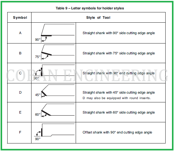
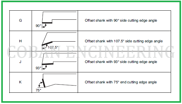
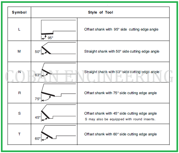
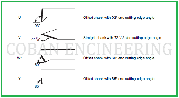
3) Holder Style: The holder style designates the shank style and the side cutting edge angle, or end cutting edge angle, or the purpose for which the holder is used. It is designated by a letter: A, for straight shank with 0° side cutting edge angle; B, straight shank with 15° side cutting edge angle; C, straight-shank end cutting tool with 0° end cutting edge angle; D, straight shank with 45° side cutting edge angle; E, straight shank with 30° side cutting edge angle; F, offset shank with 0° end cutting edge angle; G, offset shank with 0° side cutting edge angle; J, offset shank with negative 3° side cutting edge angle; K, offset shank with 15° end cutting edge angle; L, offset shank with negative 5° side cutting edge angle and 5° end cutting edge angle; M, straight shank with 40° side cutting edge angle; N, straight shank with 27° side cutting edge angle; R, offset shank with 15° side cutting edge angle; S, offset shank with 45° side cutting edge angle; T, offset shank with 30° side cutting edge angle; U, offset shank with negative 3° end cutting edge angle; V, straight shank with 171⁄2° side cutting edge angle; W, offset shank with 30° end cutting edge angle; Y, offset shank with 5° end cutting edge angle. Letter symbols for holder styles shown in the following figures;


Copyright ©2010-2023 Coban Engineering.All Rights Reserved.