- GD&T
GENERAL DIMENSIONING- International Paper Size Standards
- Technical Drawing Styles
- ISO And ANSI Projections
- ANSI Technical Drawing Views
- Technical Drawing Dimesioning Types
- ANSI and ISO Geometric Tolerancing Symbols
- Geometric Tolerancing Reading
- Taylor Principle Rule#1
- Form Tolerances
- Profile Tolerances
- Orientation Tolerances
- Location Tolerances
- Runout Tolerances
- TOLERANCES
ANSI AND ISO- Tolerancing and Engineering Standards
- Hole and Shaft Basis Limits And Fits
- ISO International System For Limits And Fits
- International Tolerance Grade (IT)
- Fundamental Deviations For Hole and Shaft Basis
- ISO Tolerance Band IT01-IT16
- Calculation Of International Tolerance
- Calculation of Upper and Lower Deviation For Shaft
- Calculation of Upper and Lower Deviation For Holes
- ISO Shaft Tolerances (3mm-400mm)
- ISO Shaft Tolerances (400mm-3150mm)
- ISO Hole Tolerances (3mm-400mm)
- ISO Hole Tolerances (400mm-3150mm)
- ANSI Standard Limits and Fits
- METAL CUTTING TECHNOLOGIES
- Terms and Definitions of the Cutting Tools
- Cutting Tool Materials
- Selection of Carbide to machine the work-part
- Identification System For Indexable Inserts
- Work-Part Materials
- Machinability and the specific cutting force
- Machinability of the Certain Material Evaluations
- Cutting Forces and Chip Formations
4) Normal Clearances: The normal clearances of inserts are identified by letters: A, 3°; B, 5°; C, 7°; D, 15°; E, 20°; F, 25°; G, 30°; N, 0°; P, 11°.
5) Hand of tool: The hand of the tool is designated by a letter: R for right-hand; L, left-hand; and N, neutral, or either hand.
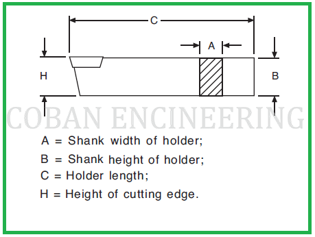
6) Tool Height for Rectangular Shank Cross Sections: The tool height for tool holders with a rectangular shank cross section and the height of cutting edge equal to shank height is given as a two-digit number representing this value in millimeters. For example, a height of 32 mm would be encoded as 32; 8 mm would be encoded as 08, where the one-digit value is preceded by a zero.
7) Tool Width for Rectangular Shank Cross Sections: The tool width for tool holders with a rectangular shank cross section is given as a two-digit number representing this value in millimeters. For example, a width of 25 mm would be encoded as 25; 8 mm would be encoded as 08, where the one-digit value is preceded by a zero.
8) Tool Length: The tool length is designated by a letter: A, 32 mm; B, 40 mm; C, 50 mm; D, 60 mm; E, 70 mm; F, 80 mm; G, 90 mm; H, 100 mm; J, 110 mm; K, 125 mm; L, 140 mm; M, 150 mm; N, 160 mm; P, 170 mm; Q, 180 mm; R, 200 mm; S, 250 mm; T, 300 mm; U, 350 mm; V, 400 mm; W, 450 mm; X, special length to be specified; Y, 500 mm.
9) Indexable Insert Size: The size of indexable inserts is encoded as follows: For insert shapes C, D, E, H. M, O, P, R, S, T, V, the side length (the diameter for R inserts) in millimeters is used as a two-digit number, with decimals being disregarded. For example, the symbol for a side length of 16.5 mm is 16. For insert shapes A, B, K, L, the length of the main cutting edge or of the longer cutting edge in millimeters is encoded as a two-digit number, disregarding decimals. If the symbol obtained has only one digit, then it should be preceded by a zero. For example, the symbol for a main cutting edge of 19.5 mm is 19; for an edge of 9.5 mm, the symbol is 09.
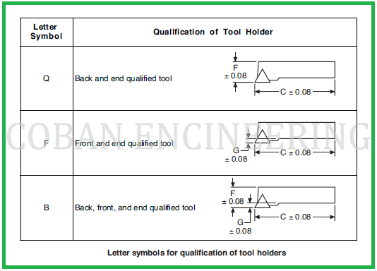
10) Special Tolerances : Special tolerances are indicated by a letter: Q, back and end qualified tool; F, front and end qualified tool; B, back, front, and end qualified tool. A qualified tool is one that has tolerances of -/+ 0.08 mm for dimensions F, G, and C. ANSI B212.5-1986 Letter Symbols for Qualification of Tool Holders for Position 10


Copyright ©2010-2023 Coban Engineering.All Rights Reserved.